
Telecom Battery Backup: System Design, Sizing & Maintenance Guide
Telecom battery backup engineering guide: 48V/-48V system architecture, battery sizing for BTS/cell towers, Tier 1-3 redundancy design, maintenance protocols, and total cost of ownership analysis. Factory direct pricing. MOQ flexible.
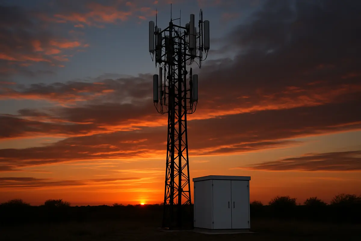
Why Telecom Networks Live and Die by Battery Backup
Telecommunications infrastructure demands availability levels that most industries never approach. The industry standard is "five nines" — 99.999% uptime, which translates to no more than 5.26 minutes of downtime per year. Battery backup systems are the bridge that maintains this availability during grid power failures, generator start-up delays, and fuel supply interruptions.
The global telecom tower count exceeds 7 million, with approximately 700,000 new towers deployed annually to support 5G rollout. Each tower requires a battery backup system sized for its specific load profile, grid reliability, and climate conditions. Getting the design right on day one prevents costly field failures, network SLA penalties, and premature battery replacements.
This guide covers the complete engineering lifecycle: system architecture, battery technology selection, capacity sizing, redundancy design, installation, and maintenance protocols. Data is based on Naradex's 18 years of manufacturing batteries for telecom operators in 100+ countries.
Telecom DC Power System Architecture
The -48V DC Standard
The global telecom industry standardized on -48V DC (negative grounding) for historical and safety reasons. At -48V, the voltage is low enough to be considered "safety extra-low voltage" (SELV) under IEC 60950, eliminating the requirement for protective grounding of the DC bus. The negative grounding convention means the positive terminal is connected to earth ground, and the -48V bus carries the load current.
Key voltage thresholds in a -48V telecom power system:
System Block Diagram
A complete telecom power system consists of these subsystems:
AC Input Stage: Utility mains (single-phase or three-phase) feeds through a distribution panel with surge protection, circuit breakers, and power metering. Diesel or gas generators provide backup AC power with automatic transfer switch (ATS) engaging within 10-30 seconds of grid failure.
Rectifier System: AC/DC rectifiers convert utility or generator AC to -48V DC. Modern rectifiers are modular (1-6 kW per module), hot-swappable, and N+1 redundant. Total rectifier capacity is sized to power the full DC load plus charge the battery bank at 0.10-0.15C simultaneously.
Battery Bank: Connected directly to the -48V DC bus through a battery distribution fuse box (BDFB) or circuit breaker. The battery bank seamlessly absorbs load during the transition between grid failure and generator start — no switching delay, no interruption.
DC Distribution: The -48V bus feeds through fuse panels or circuit breakers to individual loads: radio units (RRU/RRH), baseband units (BBU), microwave backhaul, cooling fans, obstruction lights, and auxiliary equipment.
Monitoring and Control: Power system controller provides local and remote monitoring via SNMP, TCP/IP, or serial interfaces. Monitors rectifier status, battery voltage, charge/discharge current, temperature, and alarm conditions. Integrates with the operator's Network Operations Center (NOC).
Battery Technology Selection for Telecom
Decision Matrix
12V AGM vs 2V Cell: When to Use Each
Use 12V AGM batteries when: - Site capacity requirement is under 500Ah - Floor space is limited (12V batteries stack vertically in standard cabinets) - Simplified installation and replacement is needed (fewer connections) - Budget is the primary constraint
Use 2V cells when: - Site capacity requirement exceeds 500Ah - Maximum reliability is required (individual cell monitoring possible) - Design life of 15-20+ years is needed (2V cells have longer float life than 12V blocks) - The site has dedicated battery racks with proper support structures
Battery Sizing: Step-by-Step Engineering Method
Step 1: Determine the DC Load Profile
Measure or calculate the total DC load at the site under normal and emergency operating modes:
Typical total DC loads by site type:
Step 2: Define Required Backup Time
Backup time requirements depend on the site's grid reliability, generator availability, and operator SLA:
Step 3: Apply the Sizing Formula
Battery capacity (Ah) = (DC load in watts x Backup time in hours) / (48V x Efficiency x Aging factor x Temperature factor)
Where: - **Efficiency** = 0.85 (accounts for voltage drop and wiring losses) - **Aging factor** = 0.80 (ensures capacity at end of battery life, per IEEE 485) - **Temperature factor** (from table below):
Note: Temperature factor addresses discharge capacity, not battery life. At lower temperatures, lead-acid batteries deliver less capacity — hence the derating below 25 degrees C. Battery life derating due to high temperature is addressed separately in the replacement schedule.
Sizing Examples
Example 1: Urban macro site (3 sectors, 4G) - DC load: 2,500 W - Backup: 8 hours (Tier 1, generator available) - Temperature: 30 degrees C average - Capacity = (2,500 x 8) / (48 x 0.85 x 0.80 x 1.00) = **613 Ah** - Solution: 4 strings of 4 x ND12-200 (4S x 4P = 48V 800Ah) - Or: 24 x NL2-1000 (24S = 48V 1000Ah, single string with headroom)
Example 2: Rural site (no generator) - DC load: 1,200 W - Backup: 48 hours - Temperature: 35 degrees C average - Capacity = (1,200 x 48) / (48 x 0.85 x 0.80 x 1.00) = **1,765 Ah** - Solution: 24 x NL2-2000 (48V 2000Ah, single string with 13% headroom)
Example 3: 5G macro site (high power) - DC load: 5,000 W - Backup: 4 hours - Temperature: 25 degrees C - Capacity = (5,000 x 4) / (48 x 0.85 x 0.80 x 1.00) = **613 Ah** - Solution: 4 strings of 4 x ND12-200 or 24 x NL2-1000
Redundancy Design: Single String vs Multiple Strings
Single String Design
All batteries connected in one series string. If one battery fails, the entire backup system is compromised.
Advantages: Simpler wiring, lower cost, uniform charging. Disadvantages: Single point of failure, no maintenance flexibility.
N+1 Redundant Design (Recommended)
Multiple parallel strings, each capable of carrying the full load. With N+1 redundancy, one string can be taken offline for maintenance or replacement without losing backup capability.
Example: 2-string N+1 design for a 600Ah requirement - String 1: 4 x ND12-200 = 48V 200Ah - String 2: 4 x ND12-200 = 48V 200Ah (redundant) - Total: 48V 200Ah per string x 4 strings = 800Ah total - Any single string can be removed for maintenance while the remaining strings provide full backup
String Management Best Practices
- **All batteries in a string must be identical** — same manufacturer, model, capacity, and manufacturing date - **Never mix old and new strings** — if one string is replaced, the remaining strings should be within 2 years of age - **Install string fuses or breakers** — allows individual string isolation for testing, maintenance, or replacement - **Balance string cables** — cable length from the DC bus to each string should be equal (within 5%) to ensure even current distribution
Installation Best Practices for Telecom Sites
Cabinet Temperature Management
Battery cabinet temperature is the single most controllable factor affecting battery life. Every 10 degrees C above 25 degrees C approximately halves the expected float life.
ROI example: Installing a $500 DC ventilation system that reduces battery temperature from 40 degrees C to 30 degrees C extends AGM battery life from approximately 2 years to 6 years — saving two full battery replacements ($3,000-$8,000 in battery cost) over a 10-year period.
Terminal Connection Quality
Poor terminal connections are the second most common cause of telecom battery failure after temperature:
- **Use calibrated torque wrench** — over-tightening crushes the lead terminal, under-tightening creates a high-resistance joint - **Apply anti-oxidant compound** on terminals in coastal, humid, or polluted environments - **Use copper interconnecting cables** with properly crimped lugs — avoid aluminum due to galvanic corrosion risk - **Maximum inter-cell cable length difference:** within 5% between parallel strings
Commissioning Protocol
After installation, perform these commissioning steps before declaring the site operational:
1. **Visual inspection:** Verify all connections, polarity, fuse ratings, and physical security 2. **Float voltage verification:** Measure each string voltage and individual battery/cell voltages — all should be within 0.1V of each other (12V batteries) or 0.02V (2V cells) 3. **Capacity verification:** Perform a controlled discharge test at the calculated load current to verify actual runtime meets the design specification 4. **Alarm testing:** Simulate LVD and LLVD thresholds to verify proper alarm generation and load shedding 5. **Documentation:** Record all baseline measurements (voltages, impedance, temperature) for future comparison
Maintenance Schedule and Protocols
Telecom battery maintenance follows a tiered schedule that balances battery health monitoring against the cost and logistics of site visits:
Monthly (Remote Monitoring)
Quarterly (Site Visit)
Annually (Comprehensive)
Impedance Testing: The Predictive Maintenance Standard
Battery impedance testing is the most cost-effective predictive maintenance method for telecom batteries. A single handheld impedance tester ($2,000-$5,000) can prevent costly emergency site visits and network outages by identifying failing batteries before they cause problems.
How impedance testing works: 1. Establish baseline impedance for each battery/cell at installation (commissioning) 2. Measure impedance at each annual visit 3. Track the trend over time — impedance should remain relatively stable for the first 60-70% of design life, then begin to rise 4. When impedance increases by 20% from baseline, the battery is approaching end-of-life 5. When impedance increases by 50% from baseline, the battery has failed
Cost-benefit: A $3,000 impedance tester pays for itself with the first prevented emergency battery replacement or network outage.
Total Cost of Ownership: 10-Year Analysis
Scenario: Standard Urban Macro Site (2.5kW, 8-Hour Backup)
Key insight: 2V AGM cells often deliver the lowest total cost of ownership for telecom applications — they last longer than 12V blocks (reducing replacement frequency) and cost less than gel. Gel batteries only become cost-justified in cycling-intensive or high-temperature environments where their 2-3x cycle life advantage offsets the premium.
5G Impact on Telecom Battery Design
5G base stations consume 2-3 times more power than 4G equivalents, primarily due to massive MIMO antenna arrays and higher-bandwidth processing. This has significant implications for battery backup systems:
5G battery sizing guideline: For 5G sites consuming 5kW+ with 8-hour backup requirements, design with 2V cells (NL2-1000 or larger) rather than 12V AGM batteries. The larger per-cell capacity is more space-efficient and delivers better long-term reliability.
Related Resources
- AGM vs Gel vs Flooded Battery Comparison — Technology selection deep dive - AGM Battery Charging Guide — Rectifier settings and charge profiles - UPS Battery Replacement Guide — Sizing and replacement procedures - VRLA Battery Maintenance Guide — Maintenance protocols for all VRLA types - Telecom Application Page — Naradex telecom battery solutions - 12V AGM Products — ND12 series for standard telecom sites - 2V Stationary Products — NL2 series for large capacity - OPzV Gel Products — OPzV2 series for cycling and solar hybrid